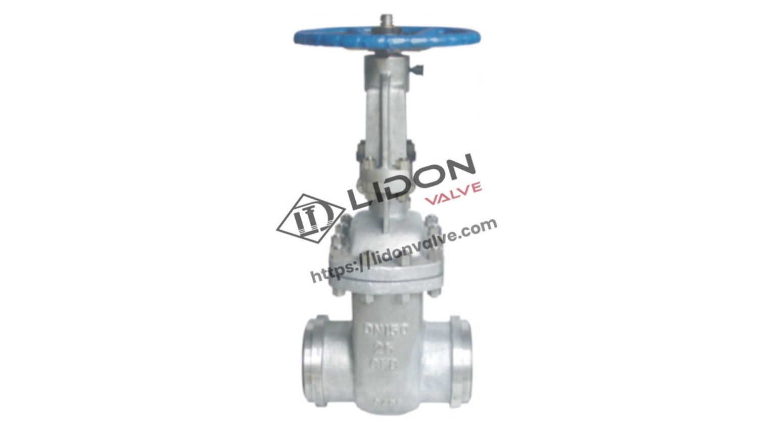
Understanding gate valve diagrams: A Comprehensive Guide
Gate valves are essential components in various industrial applications, allowing for the control and regulation of fluid flow. To fully comprehend the functioning of gate valves, it is crucial to understand their diagrams. In this article, we will explore the intricacies of gate valve diagrams, shedding light on their components, operation, and maintenance. Whether you are a professional in the field or simply curious about gate valves, this comprehensive guide will provide you with all the information you need.
The Anatomy of a Gate Valve Diagram
Before delving into the details of gate valve diagrams, let's familiarize ourselves with the basic anatomy of a gate valve. A gate valve consists of several key components, each playing a vital role in its operation:
1. Body
The body serves as the main casing of the gate valve, housing all the internal components. It is typically made of materials such as cast iron, bronze, or stainless steel, depending on the application and the fluid being controlled.
2. Bonnet
The bonnet acts as a cover for the valve body, providing a seal and preventing leakage. It also houses the stem and the packing gland, which are essential for the valve's operation.
3. Stem
The stem is a long, slender rod that connects the handwheel or actuator to the gate. It transfers the motion from the operator to the gate, allowing for the opening and closing of the valve.
4. Gate
The gate is the primary component responsible for controlling the flow of fluid. When the valve is open, the gate is lifted, allowing the fluid to pass through. Conversely, when the valve is closed, the gate is lowered, obstructing the flow.
5. Seat
The seat is the sealing surface where the gate makes contact when the valve is closed. It ensures a tight seal, preventing any leakage when the valve is in the closed position. Seats are commonly made of materials such as metal, elastomers, or resilient materials.
Understanding Gate Valve Operation
Gate valves are known for their simple yet effective operation. Let's take a closer look at how they function:
6. Opening and Closing
Gate valves operate by lifting or lowering a gate to control the flow of fluid. When the valve is in the closed position, the gate is fully lowered, blocking the pathway for fluid to pass through. To open the valve, the gate is lifted, creating an unobstructed flow path.
7. Full Flow and No Flow
Gate valves are binary devices, meaning they provide two distinct states: full flow and no flow. In the fully open position, gate valves allow for maximum flow of fluid, with minimal pressure drop. In the fully closed position, gate valves provide a tight seal, completely blocking the flow of fluid.
8. Linear Motion
The operation of gate valves is characterized by linear motion. The gate moves in a straight line perpendicular to the flow path, allowing for a quick and precise control of fluid flow.
Maintaining Gate Valves: Diagrams for Maintenance
Proper maintenance is crucial for the longevity and efficient operation of gate valves. Here are some important aspects of gate valve maintenance:
9. Lubrication
Gate valves require regular lubrication to ensure smooth operation and prevent seizing. Lubrication also helps maintain a tight seal between the gate and the seat, reducing the risk of leakage.
10. Inspection
Regular inspection of gate valves is essential to identify any signs of wear, corrosion, or damage. By inspecting the diagrams and internal components, maintenance personnel can determine the condition of the valve and take appropriate action.

